| Jetbag Filter
|
On Line: In an online bag filter, bags are cleaned row by row, even while the dust laden gas is filtered concurrently. The sequence of cleaning is controlled automatically by a sequence controller. This operates the assembly of solenoid and pulse valves which direct the air flow into the manifolds. The holes are jig drilled for perfect alignment with the venturi centre for achieving maximum cleaning efficiency.
Offline: It incorporates the advantages of a pulse jet bag filter as well asthat of a reverse air bag house. Each compartment is similar to an online pulsejet bag filter. The cleaning process consists of sequentially isolating each compartment and then cleaning the isolated compartment with compressed air. Offline cleaning is suitable for light and fine dust where occurrence of fluidization is a distinct possibility. Generally the Offline Bag Filter is employed for larger gas volumes.
|
|
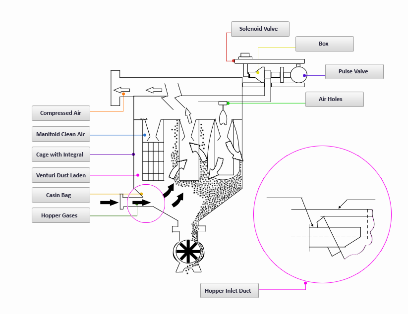 |
Pulse Jet Bag Filters - Online |
 | Regular Hopper
|
The pulse jet bag filter in its most rudimentary form basically consists of the filtration elements housed in a casing. Below this casing is a hopper with a discharge valve, to continuously remove the dust that is collected on the bags. The entire unit is supported from the ground on structural legs. A caged ladder provides access to the top of the unit for maintenance. The dust laden air enters through the hopper by suction (normally) or (positive pressure). The heavier dust particles fall off at the entry itself, while the lighter dusts get carried upward to the bags.
The dust gets deposited on the outer surface of the bags and the clean air moves upward from the center of the bags through the outlet plenum to the top air outlet. This is known as filtration. The dust collected on the outer surface of the bags is removed in a pre-determined cycle by a momentary pulse of high-pressure compressed air. The compressed air moves from an air reservoir or compressed air header via the particular pulse valve into the compartment manifold and thereon into the bags in the row beneath it. The pressurized entry of compressed air through the venturis into the bags, inflate the latter and the dust cake formed on the bag surface slides down in the form of flakes. The cages help the bags retain their original shape once the effect of the compressed air is gone. This completes the cleaning process. The dust slides down the hopper walls to the rotary airlock valve. The latter is a rotating device which discharges the dust continuously, all the while maintaining an air seal.
|
|
 | FlushMounted
|
| Transfer points involving two conveyors or from one conveyor to / from other material handling equipment often involve isolated point(s) where free standing bag filter(s) can be an expensive proposition. Space availability on ground is also an issue at times. Typically, these insertable bag filters units are devoid of any hopper. The unit can be suitably positioned on the conveyor directly. On pulsing, dust falls back onto this conveyor, thus avoiding a need for a separate dust discharge hopper. Depending on the height of fall of dust, two such insertable bag filters may be required - one at the end of the discharging conveyor and one on the receiving conveyor. When a single unit is used, it is normally on the receiving conveyor - as shown in the adjoining figure - this being where generation of dust is higher due to impact. These type of units are also optimal solutions for venting of bins / silos / hoppers. The units in this construction are mostly standardized and pre-engineered, though customized variations can be offered where necessary.
|
|
 | FlushMounted 2
|
| The construction here is similar to an insertable bag filter; however in this case, the casing of the bag filter is circular instead of being rectangular. The top cover could be a dished end - as in the adjoining figure - which is used for high positive design pressure or vacuum, as is typically a situation encountered for applications related to venting of silos / bins connected to pneumatic conveying systems.
|
|
 | Casing Entry
|
| Here the dirty gas enters the casing - through the inlet- cum-bypass damper in boiler bag filters (as in the sketch alongside) - and flows into a central chamber formed by perforated sheets. The gas flow towards the bags is partially through the perforations and partially upward from below of the sheets, ensuring better gas distribution and the separation of heavier dust respectively. The lighter dust gets carried upward to the bags. This gets deposited on the outer surface of the bags and is removed by a pre-determined cycle by a momentary pulse of high pressure compressed air as in the case of a typical hopper entry type of bag filter.
|
|
 | Tangential Entry
|
| The gas enters into the bag filter tangentially at the bottom of the casing. This gives the dust laden gas a circular motion which helps in removing the heavy & coarser particles that are present in the gas stream in a manner similar to a cyclonic collector. These collected particles are directly discharged into the hopper. It is only the very fine particles that get carried to and collected on the bag surface. Thus the total dust load on bags is reduced making it possible to maintain lower pressure drop across bags. This also permits the use of lesser frequency of bag pulsing, which in turn increases bag life.
Due to its circular construction, these bag filters can withstand more +/- pressure as compared to normal rectangular bag filters. The circular construction of bag filter also ensures leak proof ness. The possibility of dust accumulation inside casing (on edges etc.) is eliminated. Due to the arrangement of bag as shown in the image alongside, each and every bag is exposed to the dust laden gas. The swiveling arrangement shown enables the top cover to be pushed to on one side and lifting of the same. Due to special top cover and outlet plenum construction the entry of outside air is avoided.
|
|
 | Bag Cage
|
| In the Pre-separator extended hopper type of unit, the dirty gas enters in the common inlet plenum formed as an aisle between the two filter modules resulting in pre-separation of the dust laden gases. From there it flows to both the modules undergoing filtration as in a regular unit.
The cleaned gases travel back to the common outlet plenum from the individual clean air plenums and then flow out through the outlet duct to the ID fan.
|
|
 | Typical Immersion
|
| The phenomenal growth of the Cement Industry has seen the advent of plants of much bigger size. The conventional bag filters have been found to be inadequate to handle large gas flows in excess of 6,00,000 m3/hr. This is due to severe limitations on aspects like high gas flow per bag, high velocity of gases through bag filter, higher pressure drop across filters, high space requirement and high compressed air consumptions.
|
|
Pulse Jet Bag Filters - Offline |
 | Offline Bag Filter OpenUp
|
| An Offline Bag Filter is used when the dust in gases is very light and fine. In an online bag filter, the dust that is dis-clogged from a row of bags may be picked up by the adjacent row of bags as the latter is under suction. The dust may remain in suspended condition - especially if it is light and / or fine - the reverse upward gas flow not allowing the dust to settle in the hopper. This phenomenon is called fluidization of dust. This fluidization of dust results in high differential pressure across the bag filter, abrasion and ultimately choking of bags. This is where an offline bag filter is employed.
|
|
 | Offline Bag Filter Working
|
| The Offline Bag Filter typically contains 4 to 6 bag filter compartments or modules. Each compartment is similar to an online bag filter. However, her the gas flow through a compartment is stopped temporarily when the pulse cleaning of the bags is to be done in that compartment.
The dust dislodged from the bags settle easily in the hoppers because of the absence of any counter-current gas movement in this compartment. The dust so collected is discharged from the hopper through the rotary airlock valve.
During this time the remaining compartments keep filtering the gases as usual. Each compartment is cleaned one after another in this manner.
The star ting & stopping of gas flow through individual compartments is achieved through a compact pneumatically operated poppet damper system located at the outlet of each module. While the pulsing in individual compartments are controlled by means of a compartment sequential controller, the sequence of operations of the different compartments with respect to each other are controlled by a master sequential controller.
|
|
Components and Types |
Fabrics |
| Fabric Type |
Can withstand maximum temp |
Chemical Analysis |
| Flex abrasion |
Moisture |
Acid |
Base |
Organic |
| Polypropylene |
90oC |
Good |
Excel |
Excel |
Excel |
Excel |
| Acrylic |
120oC |
Good |
Good |
Good |
Good |
Good |
| Polyester |
130oC |
Excel |
Fair |
Fair |
Poor |
Good |
| Nomex |
190oC |
Good |
Poor |
Poor |
Fair |
Good |
| Fibreglass |
260oC |
Poor |
Excel |
Excel |
Excel |
Excel |
| PPS |
180oC |
Good |
Good |
Good |
Excel |
Good |
|
 | Filtration Woven Fibre
|
| In a woven fabric, the particle gets collected by one or more of the machnisms(like interception, internal impaction etc.) resulting in a build uo of 'dust cake' which is mostly on the surface.
|
|
 Filtration Non-Woven Fibre
|
| In a non-woven fabric, the filtration is not only on the surface resulting in a build up of 'dust cake' but also in - depth.
|
|
 | Snap Ring Bag
|
| Cages are wire frames placed inside pulse jet filter elements to provide support to the fabric as flexing occurs during filtration and cleaning cycles. Configuration of a frame generally follows the shape of the filter elements, i.e., circular, oval, flat or star- shaped. Cage for long filter elements are made in sections which snap together for easier handling. Wear points on filter bags may develop at the horizontal supports.
Cage designs to reduce these points increase the number of vertical wires and reduce the horizontal supports. Protective coatings on cages can extend the life of the cage and the bag. Coatings such as vinyl, epoxy, zinc, and Teflon may be used.
|
|
 | Solenoid Pulse Valve
|
| The pulse of compressed air is controlled by series of pulse solenoid valves that are placed on air reservoir. These in turn are connected to compartment manifold pipe, which open above the venturi of each bag in that row.
The diaphragm of the pulse valve is closed as the compressed air is trapped between diaphragm and solenoid valve orifice. When the solenoid valve is energized through an input signal from the sequential controller, the trapped air flows from the top of the diaphragm through the orifice of the solenoid valve.
The inflowing compressed air lifts up the diaphragm and flows through the outlet of the pulse valve. Again when the solenoid valve is de-energized, the air gets trapped, closing the diaphragm as a result of pressure equalization.
The next solenoid valve gets energized and the entire process is repeated sequentially in cycle.
|
|
 Rotary Airlock Valve
|
| The rotary air lock valve maintains an air seal preventing its passage into the hopper from below.
|
|
  
|